Wolfys Stainless Steel Brewery Build Log (picture intensive)

The forum for discussing all kinds of brewing paraphernalia.
Wolfy

Wolfys Stainless Steel Brewery Build Log (picture intensive)

Post by Wolfy » Fri Jul 27, 2012 10:27 pm

It's taken more than 6 months, and is one of the reasons I have not been active on these forums, but my new brewery is at the stage where (while it's not quite complete) it can make wort that I can turn into more-than-acceptable beer ... so I thought I'd share the details/process with everyone here. Some of the details are Australian-centric and there is a considerable amount of info and photos, so I've tried to focus on what might be interesting, and provide links to my blog-posts (where you'll often find long-rants on each part of the process).

Please feel free to ask any questions or for more information about any part of the process - especially if I skipped over something important.

Introduction:
The main purpose of posting this is to (hopefully) show how I've done stuff and essentially prove that if I can do it, anyone can. While there is not much new, different, special or unique, I'm presenting the info in the hope of inspiring others with some of the ideas or to DIY their own brewery setup.

Disclaimer:
[*] Most ideas, designs, concepts and information were borrowed, copied or learned from others on these forums or other online resources. i do not claim such as mine or suggest they are, but present them here as what I've done for my own needs and purposes.
[*]I have no skill with power tools, handy-man stuff, measuring shit or building things, so no matter what level inept skill level with such things, anyone can do this.
[*]My delicate office-worker hands get blisters just at the thought of manual labour, so again, if I can do it anyone can.
[*]There are probably other/better ways to achieve the same results, especially when working with tools and stuff. It may be that I overlooked or did not know better, so any/all advice is welcome for future improvement, especially in regard to tools, techniques or build methods.
[*]Use some common-sense and practicality if you decide to follow any suggestions or advice. While I honestly feel that if I can build stuff like this, anyone can, never try to do more than you can manage, always use appropriate tools, appropriate protective equipment and don't do anything that could injure yourself or others without first carefully considering the consequences.
[*]At the time of posting, I have not injured myself or others in any major way, however, if you do follow any suggestions or advice, please realize that you do-so at your own risk and nobody but yourself is to blame for any adverse consequences, damage, injury or worse.

Planning and Overview
Blog post
Objectives:
[*]Appropriate equipment to brew the best and most consistent beer possible (for me at home).
[*]Keep build costs to an absolute minimum.
[*]Maintenance and cleaning easy and hassle free.
[*]Able to brew double batches if required.
[*]Minimise or eliminate the need to manually lift hot wort/water.

Major build decisions:
[*]3-vessel system
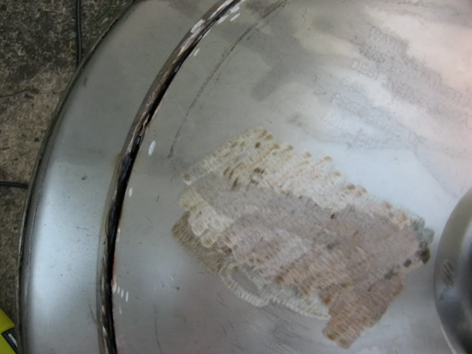
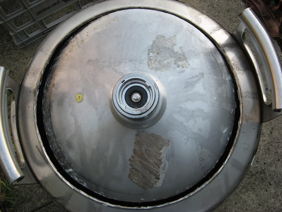
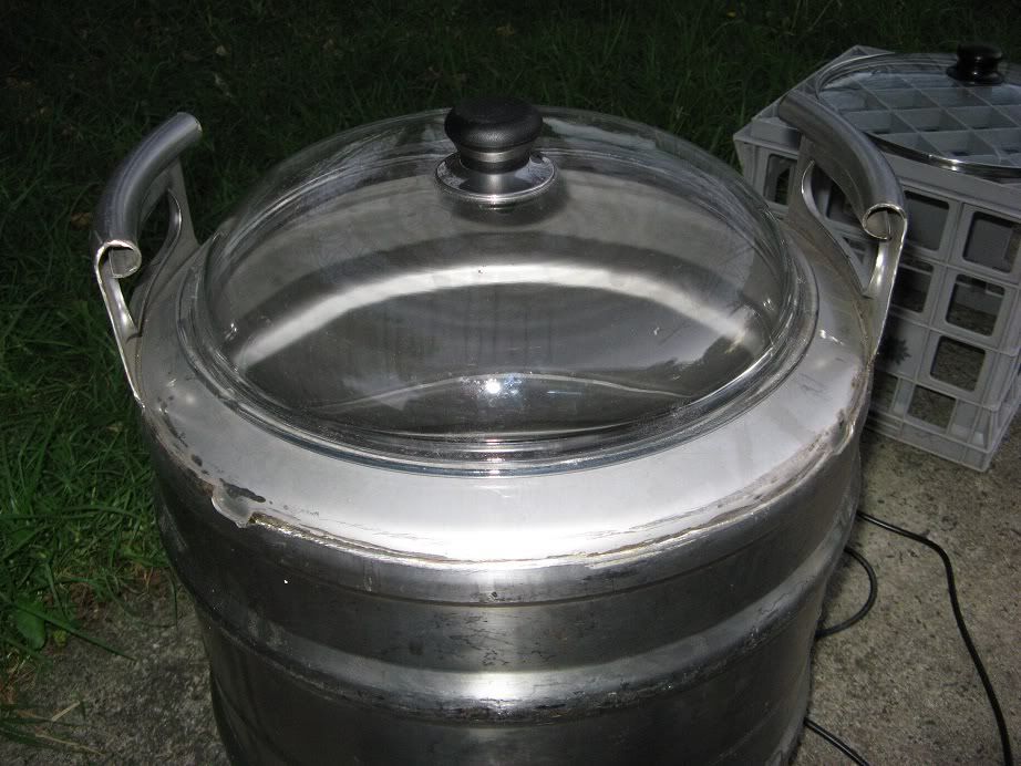
[*]All stainless construction (based on 2nd-hand 50L 'euro kegs')
[*]All electric
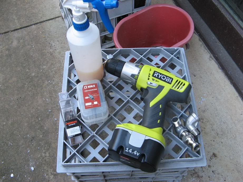
[*]Silicon hose and stainless cam-lock connections
[*]Pump for liquid transfer
[*]DIY for everything possible
[*]Careful consideration of each component, source and cost (tight-arse shopping)

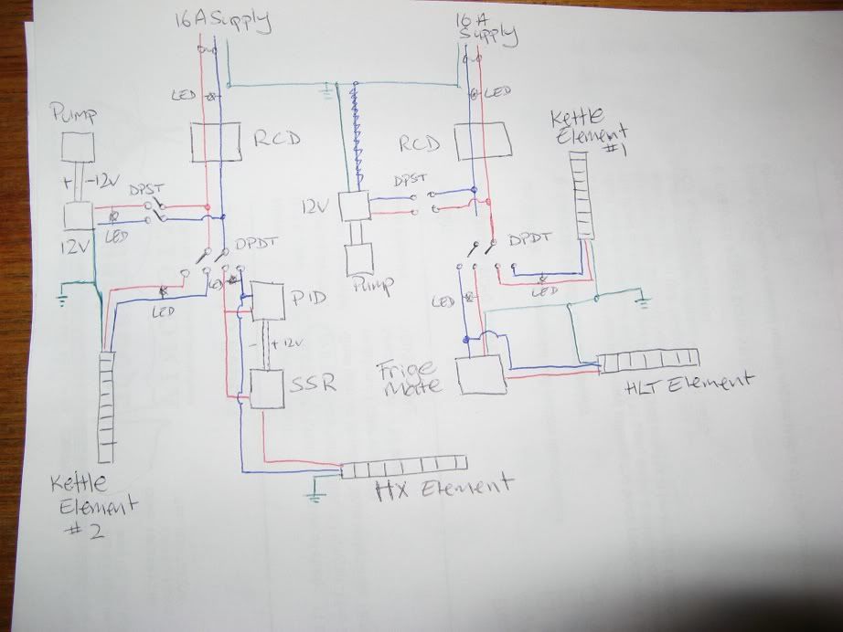
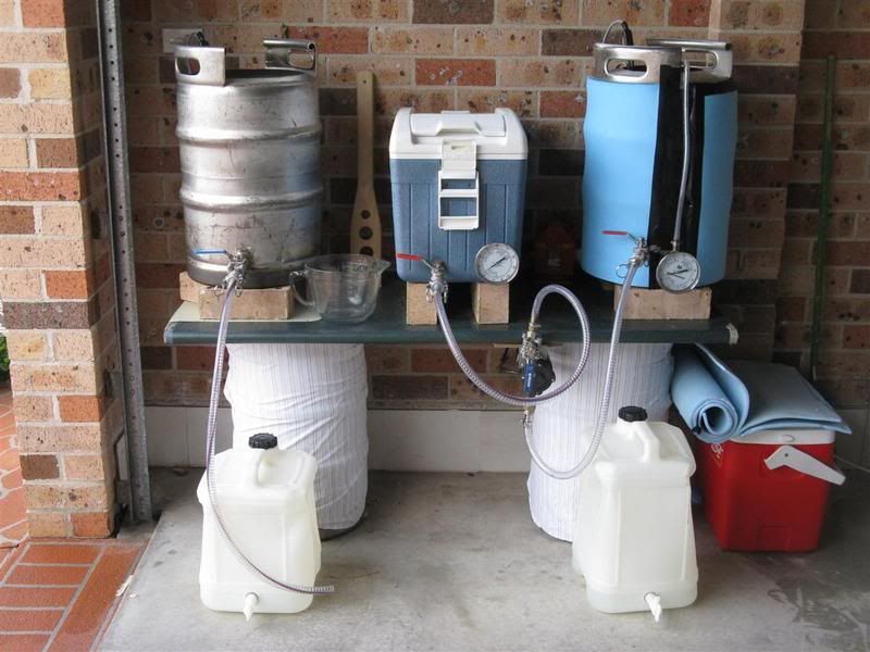
Initially I was planning to build a single-level system with a single pump, something very simple and easy like this or this. However, since I prefer to fly-sparge, the design quickly evolved into a 2-tier setup and over the last six-or-so months, the sketches on backs-of-envelopes and other bits-of-paper have evolved a little:
Image

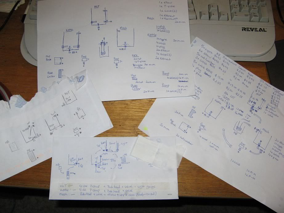
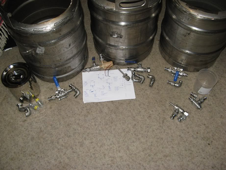
Final setup included 3x 2nd-hand 'euro' beer-kegs, plate-chiller, hop-back, a little-brown-solar-pump and a HERMS.

With my old setup, I often had trouble both hitting and maintaining the correct mash-temperature, which meaning quick additions of boiling or cold water, having to do random on-the-fly decoctions or other stuff. While the HERMS adds a deal of complexity and additional expense, it should allow mash temperatures to be controlled and stepped in a much more precise and accurate (and repeatable) way to make brew-days easier and more relaxing.

Wolfy

Re: Wolfys Stainless Steel Brewery Build Log (picture intens

Post by Wolfy » Fri Jul 27, 2012 10:32 pm

Keg Cutting
Blog post

Since they are sometimes called 'Euro kegs' I presume you can get these types of 50L stainless kegs over in the UK.

To convert the used beer kegs, they need the tops cut out of them. Google and YouTube show all kinds of complicated ways to do this, including using a jig or a plasma cutter. Since I had not done anything like this before, I did try to follow some of the advice, but found most of it pretty useless and the actual procedure (outlined below) much simpler and easier than I imagined.

The only major tool needed to cut the keg-tops is an angle grinder, a thin steel cutting disk and a thicker steel grinding disk, however the cheap disks (shown below) worked well:
Image

The first thing to do is depressurize the keg, put a rag over the valve and pushing down with a heavy screw driver (the keg shown below has the spear removed so no chance of pressure-buildup). Then mark out the top of the keg, I found a 30cm glass-fry-pan lid at an Op-shop which will make an ideal lid, so I just traced around the outside:
Image

Attach the thin metal cutting disk to the angle grinder and run it -lightly- around just inside the marked line:
Image

Now that we have a groove to follow, continue to run the angle grinder around that groove. If you have not yet removed the top collar of the keg - and especially if you don't plan to use a lid of a specific size - there is no need to mark the cutting circle, simply place the shield of the angle grinder against the collar and use that as a guide as you cut around the top of the keg.

Continue to work the angle grinder around the groove, keeping the cutting depth even all the way round, this should help preserve the cutting disk and if you do not concentrate on one section for too long it allows the stainless steel to cool before you come back to cut on that location again:
Image

After running the angle grinder around the top of the keg a few times, it will eventually cut through the top:
Image

At this stage, it's best to keep the keg-spear in-place (but ensure the keg is totally depressurized) that way the section of keg-top has something to balance on as it's cut out:
Image

Change to the steel grinding disk and clean up the hole and edges, if fitting a lid ensure that it correctly fits the hole. Run the grinding disk over, around and under the hole to smooth it of and remove any jagged bits of metal. I found that by resting the guard of the angle grinder on the edge, guiding it backward grinding and smoothing the edge gradually around the circle allowed a good level of control and ensured that the (generally) circular hole remained (pretty much) circular:
Image

Once the edges have been cleaned up with the grinding disk, its useful to smooth off the edges even more using a file, dremel tool or wet-dry sandpaper. Continue working around the edge until it is smooth and clean and you can run your hand around without cutting yoruself or getting metal-splinters. After a bit of work (maybe 1/2 hour all up) the top of the keg has been cut out, smoothed off and lid fitted:
Image

Wolfy

Re: Wolfys Stainless Steel Brewery Build Log (picture intens

Post by Wolfy » Fri Jul 27, 2012 10:37 pm

Keg Drilling
Blog

Drilling kegs is another topic that is a common source of discussion (and contention) among home brewers looking to build their own systems. After using the cheap step-bit to drill the tap-holes on my beer-fridge, I knew that it would not be up to the task of cutting holes in the beer kegs. But trust me, it's not hard, and with the right tools it's it's actually very easy.

In this case the right tools are quite simple, a drill capable of controlled sustained low speed (less than 300RPM) combined with a decent amount of torque, and a Tungsten Carbide Tipped (TCT) Hole Saw of the appropriate size. The hole saw is an expense should last a life-time (some have drilled more than 80 kegs and it's still working fine). The only other thing needed is some cutting lubricant or WD40 to help keep things cool while drilling and prevent work-hardening the stainless and/or ruining the hole saw.
Image
20mm hole saws are the best size for 1/2 inch fittings, but you do generally need to make the holes just a fraction larger once they are cut, 32mm hole saw is the exact right fit for the heating elements (I think it's 1 inch size).

Mark the location to be drilled, ensuring that it's not too close to any seams or curved edges on the keg, using a washer as a spacer helps to ensure that the fitting will sit correctly once fitted in the drilled hole.
Image

If your DIY skills are like mine, a piece of tape will stop the drill bit slipping on the curved stainless surface while drilling the pilot hole.
Image

Low speed setting on the drill, some decent pressure, stopping every now and then to spray on some more cutting lubricant ...
Image

... and in just a few minutes the hole saw should punch through the stainless leaving a nice clean hole.
Image

The 20mm size hole saw is just a fraction too small for most 1/2 inch fittings, interestingly I have a range of fittings and the hole size required seems to depend on which fittings are going to be used, so it's good to check the individual fitting to ensure that you don't make the hole too big.
Image

A small amount of manual labour with a file, a dremel type tool or anything similar will widen the hole just enough so that the fittings slip inside.
Image
This is the thermowell which will be fitted to the base of the HLT.

With the right tools, drilling neat and clean 1/2 inch keg holes is actually a very simple and easy procedure that anyone should be able to do.
Image
Last edited by Wolfy on Fri Jul 27, 2012 10:52 pm, edited 1 time in total.

Wolfy

Re: Wolfys Stainless Steel Brewery Build Log (picture intens

Post by Wolfy » Fri Jul 27, 2012 10:51 pm

Plumbing - fittings
Blog post

Since I can't weld, the decision to use weldless fittings was made for me, as was to use all stainless and since 1/2 inch size is standard for home-brewers that was a default choice also. While the fittings used are all 1/2 inch, they are a combination of NTP (USA tapered thread) and BSP (parallel thread). Some were sourced from the USA, many cheaply from China via Ebay and some locally from specialty stainless vendors (which worked out to be much the same price as Ebay/China in the end)

USA 'SnapLock' camlock fittings were about half the cost of similar local products.
Image

The two 1/2inch thermowells have both a 1/2 inch thread that screws into the keg and also a 1/2 inch thread to fit a probe - most other thermowells are designed differently.
Image

After checking the prices from four local vendors, and two USA based websites, Chinese Ebay fittings appeared to be about 20-40% cheaper, however it turned out that 'cash price' at local specialty stainless vendors was much the same but the fittings were usually of better quality. 3piece valves for kettle and mash tun, 2piece for HLT and pump:
Image

Proof that at 1/2 inch size BSP and NPT fittings being inter-changeable (for home-brew purposes and pressures):
Image
From left: American NPT camlock, Australian BSP nipple, Chinese NPT cross, Australian BSP elbow, Chinese NPT nipple.
All these fittings fit snugly and with or without plumbing tape are tight and secure. At 1/2 inch size the only real difference between the NPT and BSP fittings is a difference in thread-pitch, so with some plumbing tape and a little care they all mate together without issue (but I'll make sure I provide an update if I drip boiling wort all over my toes once they are in use). ;)

Hindsight is a wonderful thing, and the conclusion I made (after putting it all together) is as follows:

Tapered fittings (NPT) work best for pipe-to-pipe type connections, such as attaching valves to fittings or camlocks. The tapered thread, combined with some thread-tape, locks the fitting in place and prevents leaks without additional seals or gaskets.
Image

However, NTP fittings are much less useful for bulkhead-type connections through keg walls. Due to the tapered thread, the nut or fitting must tighten exactly as it compresses the gasket/or washer against the wall. However, the fitting can easily lock-tight too quickly (and not seal to the side of the vessel) or not tighten quickly enough (potentially allowing for leaks along the thread). So additional spacers- silicon (not visible in the picture) and steel washers are required:
Image

On the other hand parallel threaded fittings (BSP(P)) work much better as bulk-head connections. Thread-tape prevents leaks along the thread and the fittings tighten securely against the side of the vessel, meaning that a water-tight seal can be made with just a locknut and a silicon o-ring:
Image

With this in mind - and knowing that at 1/2 inch size both BSP and NTP threads mate without problem - bulkhead type connections through the wall of a vessel would be made best with a parallel BSP thread, while fitting-to-fitting connections like the ball valves, are best using tapered NTP thread.

The Chinese Ebay supplied lock-nuts have an o-ring groove cut in them so the easiest and cheapest method for sealing through-keg bulkheads is simply to use the nut and a silicon o-ring (thermowell picture above). However as the fitting is tightened the o-rings can deform or break easily making them less than useful, and essentially useless in any situation that does not have a channeled-nut for them to sit inside. As a consequence many of the fittings (especially if they were through the keg with NTP) required both a silicon washer and stainless shim-washer. Most bulkhead fittings were sealed on the inside in order to to stop the water/wort from getting into the threaded connection and between the fitting and the keg-walls.
Last edited by Wolfy on Fri Jul 27, 2012 11:05 pm, edited 1 time in total.

Wolfy

Re: Wolfys Stainless Steel Brewery Build Log (picture intens

Post by Wolfy » Fri Jul 27, 2012 10:55 pm

Electricals / Control Box
Blog post hereand here.

The addition of 3x electrical heating elements, HERMS, PID, SSR and HLT temperature controller, combined with the fact that the house's electrical wiring does not include RCD's (Safety Switches), means that the electrical stuff was much more complicated than I really wanted.

The various electrical bits ended up as follows:
1x 2200W Electrical heating element for the HLT.
1x 'Fridgemate' temperature controller to control temperature in the HLT.
2x 2200W Electrical heating element for the Kettle (with the option of controlling one via the manual setting on the PID).
1x 2000W 'cheap-kettle' element for the HERMS.
1x PID to control HERMS/mash tempeature
1x SSR between the HERMS element and controller
Other bits for the electrical control box include:
2x 20A RCD/MCB
2x DPST switches
2x DPDT switches
8x 240V LED control lights
Wires, cables, cable joiners, cable glands not shown in the photo and a box to put it all in:
Image

After a few rough sketches the circuit diagram ended up something like this:
Image

There are a number of reasons - legal and safety - why 240V DIY is not recommended, or even legal (if you intend to plug it into the power-point), so get someone with the appropriate certificate to help you out or do the work for you.

When completed the control box looks like this:
Image
The control box uses cables instead of GPO's (Power points, that would have made it look neater) because I had an abundance of left-over computer type cables, which the electric kettle (HERMS), heating elements and pump 12V adapter all use - so it was cheaper and easier to use those, especially in the small sized control box.

Image
As for how things work: Power-in via the two middle gray power-cords directly through the RCD/MCB's. The white and middle black cords are switched (two central switches) for the pump(s) or anything else needed. On the left is the HLT power, controlled by a TempMate digital controller - I had an unused one and they allow for 20A relay, which makes it more suitable than cheaper STC1000 type controllers. On the right is power for the HERMS element, controlled by the PID via the SSR. The last two black power cords (lower outer edges) are direct power for the two kettle elements, switched (via DPDT switches) so that only one of those or the HLT/HERMS can be on at any one time.

Wolfy

Re: Wolfys Stainless Steel Brewery Build Log (picture intens

Post by Wolfy » Fri Jul 27, 2012 11:04 pm

Perforated Stainless filters/false bottoms
Blog info

A commercial-keg-mash-tun false bottom does a good job solid job, but they're not cheap. Since I decided to drill holes in the bottom of the kegs for the outlet valves, I essentially needed two false-bottoms and a filter for my hopback. The perforated stainless (2mm hole-size 47% open area 0.55mm thick stainless sheets) came in 500x500mm sheets and while the hole-size is the same as commercial-type false bottoms, the open area was a little greater and the steel was also much thinner.

The good thing about the 500x500 sheet was that I should be able to make the mash-tun false bottom, kettle filter and the two hopback filters from the single sheet:
Image
(Being able to use 1 sheet for 4 different filters means it worked out much cheaper in the end)

With a little care the perforated stainless was relatively easy to cut with a cutting disk on the angle grinder:
Image

After cleaning up the edges with a grinding disk and a hand-file, the false bottom fitted in the keg mash-tun well. However, since it's thinner than the commercial false bottom, it can't easily be bent into a dome, and it may struggle to hold the weight of the mash.
Image

So I made some stand-offs from threaded pipe fittings, after a little bit of work with a grinding disk on the angle grinder, they fit under the false bottom, provide support and should allow the wort to easily drain:
Image
(Obviously this is showing it on the outside for purposes of the photo, not the inside where it will be fitted)

The bottom-draining-kettle-filter was a little smaller and slightly less round, but it still works fine:
Image

Filter-plates for the hopback were more time consuming to make due to the smaller size, my inability to measure the required width exactly and the fact that they must fit inside the container exactly:
Image

But with some time and patience, I was able to make two round filter plates that fit exactly inside the stainless container:
Image
Last edited by Wolfy on Fri Jul 27, 2012 11:18 pm, edited 1 time in total.

Wolfy

Re: Wolfys Stainless Steel Brewery Build Log (picture intens

Post by Wolfy » Fri Jul 27, 2012 11:13 pm

Cleaning

I figured it was a good idea to ensure that it was clean - especially the imported fittings. All the fittings had a bath in hot water and sodium percarbonate, then a citric acid bath and a rinse in water before drying:
Image

The kegs will also get a wash with sodium percarbonate and - especially anywhere I have drilled, cut, filed or grinded - a good scrub (with a non metallic kitchen scrub-mat-thing) with some Stainless Steel Cleaner (which contains Oxalic acid, citric acid and other random stuff including AES, K12, ETA-2NA) which should help ensure that the steel is passivated anywhere that that I've worked on it:
Image

The first batch of Chinese fittings were not that great quality, they'll still work fine and I'll use the fittings in non-critical areas like the sight-glass on the HLT, but still the workmanship was a bit shoddy:
Image
This is one reason why I'd suggest using fittings from a reputable local supplier, usually there are a few industrial/chemical fitting suppliers that are not too hard to find locally, just talk to them some about what you need, and explain you don't need the expensive high pressure stuff, and you might even get what you need at a good price.

The other thing to realize is that fittings do not appear to have a standard size. While they are all 1/2 inch fittings, and all mate together without much issue, the outside diameter, length and even thread-length of the fittings can vary depending on where and when they were purchased:
Image
Each of these fittings is lined up exactly on the edge of the bench, however each is longer, taller or have longer thread-length than the other. Again it's not a major issue, however, it's something to consider if you're designing stuff that depends on specific size fittings.

When I washed all the fittings and put then on a towel to dry, they had a few drops of water on them, but I thought nothing of it. However when looked a day later the external-body-bolts on the (Chinese Ebay-sourced) 3-piece ball-valve have rusted:
Image
Image
These were supposed to be all 316 grade stainless, and while the bolts are stamped 'A2' - which means they should be 304 grade stainless - they're clearly not if they've rusted after drying with a few spots of water on them. Interestingly these were purchased from two different Ebay vendors, so I'd guess that either the manufacturer or distributor has cut some corners or something. Both vendors were quick to offer refunds, and after some care and repasivating them with the stainless cleaner (hence the picture above - it's great stuff!) they've been fine since.

Wolfy

Re: Wolfys Stainless Steel Brewery Build Log (picture intens

Post by Wolfy » Fri Jul 27, 2012 11:16 pm

Ball valves
Blog rant

Even after their bath in sodium percarbonate, the ball valves still had a rather nasty chemical/grease/manufacturing smell to them. Since I didn't want this in my beer, I pulled them apart and gave them a good internal clean and removed all the industrial-type grease that was packed around the ball and seals. When reassembling them I used a very small amount of food-grade keg-lube, but since they will not be turned on or off very often, it was probably not necessary. Interestingly, now that I've disassembled, cleaned and reassembled them, they actually open/close much easier than before - which is a surprise because usually I break shit when I pull it apart or it never goes back together the same. ;)

Ball valves are probably the most common type of tap or valve used in home-brewery situations, because they can be disassembled and cleaned inside and out. 3-piece valves have more pieces and are slightly easier to clean when pulled-apart (and they have a better bling-factor) however the 2-piece valves are just as easy to disassemble and with a rag or brush very easy to fully clean inside.
Image

3-piece ball valves are disassembled by undoing the 4 body-bolts, and while this allows the valve to be taken apart while one end is still attached to the fitting. When reassembled two Teflon seals hold/seal the ball in place as well as providing a leak-proof seal between the three pieces of the valve. 2-piece valves are disassembled by unscrewing the two body parts, so as well as the two Teflon ball-seals, 2-piece valves have an additional smaller (and somewhat insubstantial and apparently easier to mangle) Teflon seal between the two body pieces.
Image

Both 2 and 3-piece valves can easily be disassembled for full cleaning, and from a home-brew perspective there is probably not much difference between them, but while the seals in the 3-piece valves do appear more substantial, 3-piece valves are also about 30% to 50% more expensive than similar 2-piece valves.

Wolfy

Re: Wolfys Stainless Steel Brewery Build Log (picture intens

Post by Wolfy » Fri Jul 27, 2012 11:25 pm

Sight Glass
Blog

A sight-glass on the HLT will help measure water into the mash and also (hopefully) be a visual reminder for me not to let the element in the HLT run dry (which I've done once out of 4 brews so far, so the idea was good but in practice I got distracted and forgot to turn the element off). Most sight glasses are made from Polycarbonate, but not all information suggests its food-safe so I opted to use the cheaper and easier (but not as transparent) silicon hose.

The sight 'glass' for the HLT is very simple; a couple of stainless elbows and nipples, a few washers and a lenght of silicon hose, and hose clamps to hold it in place:
Image

Since the silicon tube is not very transparent, I borrowed the little ball-thing from a kitchen kettle and added a couple of small washers that sit on the elbows so that it does not float away or get lost:
Image

Completed, with insulation on the HLT:
Image

Due to the positioning of the elbows (and the curve at the top and bottom of the keg) and the elbow 'height', the lowest volume marking displayed is 13L and the highest 37L (the heating element is exposed at 10L) so as long as the water level is shown in the sight glass it will not boil-dry. Completed, marked and set-up it looks like this:
Image

Due to the thickness of the insulation, a hex nipple was needed on the outside of the keg to 'space' the elbows out far enough, so on the inside the fitting looks like this:
Image

At the top (photo above) the fitting comprises (from the inside):
Nut - washer - flat silicon washer - keg wall - hex nipple - elbow.
The bottom fitting did not need the extra washers so:
Nut (with o-ring groove) - o-ring - keg wall - hex nipple - elbow.

In the first photo of this post (bare keg with no insulation) the elbows could sit closer to the keg-wall so the fitting hex-nipple could be installed on the inside of the keg (from the inside):
Hex nipple - keg wall - flat silicon washer (or o-ring) - elbow.

Wolfy

Re: Wolfys Stainless Steel Brewery Build Log (picture intens

Post by Wolfy » Fri Jul 27, 2012 11:29 pm

Insulation
Blog rant

Buffed and polished stainless kegs, look good and add a very nice bling-factor. However, I wanted it to be more about making good beer than looking good - besides it's not as if anyone, except myself, will be looking at the new setup anyway. While it is uglier than polished steel, insulated kegs are logical and sensible, and while the energy-cost-savings are likely to be small, they should help. In addition since it will be electric-heated, there is no problem with open flames or melting insulation to worry about.

A neighbor was throwing away this camping mat/insulation/stuff, it's about an inch thick with black-rubber-stuff on one side and blue on the other. The pipe-insulation was on chuck-out special at the hardware shop and does a good job on the silicon hose, however, it does make them more cumbersome and difficult to work with, so I'm going to find a way that it can be attached when the hose is in place (during the mash for example) but then easily and quickly removed after (which will also help with cleaning).
Image

The insulation was cut into strips 15inches high and 52-53inches long, the 32mm hole-saw easily made some holes for the fittings.
Image

The bottom layer of insulation was a little more difficult to install fit, since it didn't really want to stick down in place.
Image

But copious quantities of tape stuck it in place.
Image

A couple of rolls of silver-Aldi tape and all three kegs were wrapped up, and while they look short, dumpy and ugly now, the latex does show off their curves. ;)
Image

The bottom-insulation made attaching the fittings/valves a little more difficult than it needed to be, so with some work with the knife, I cut out a wedge:
Image

And with some more tape, it goes back together like this:
Image

Wolfy

Re: Wolfys Stainless Steel Brewery Build Log (picture intens

Post by Wolfy » Fri Jul 27, 2012 11:34 pm

Fit-out, Leak Test & Burn-in
1000-word blog rant

Filling the kegs with water resulted in a few minor leaks, and so some fittings needed to be tightened or re-assembled, but by the time I was finished all of the seals were water-tight first time. Once that was done it was time for a burn-in test, or more correctly a boil-in, by connecting the element directly to the power-socket and running it for about an hour. I don't think these elements are available in the UK, since they are imported (from China) by a LHBS specifically for these types of home brewing applications:
Image

Probably something that could be skipped, but in this case the silicon seal 'slipped' - likely due to the fitting being over-tightened - after about 45mins and ended up spilling boiling water all over the floor:
Image

Since I was a little lax in cleaning up after cutting, drilling, filing and grinding, it's possible that bits of metal were left inside the keg which caused a little bit of surface rust after the first test:
Image

The Stainless Cleaner (like I said earlier, its great stuff), a scrubby and a bit of rubbing removed them fairly quickly.
Image

And it looked like new again, next time I'll be more pedantic about cleaning things after playing with power or hand tools.
Image

After the 1 hour test-boil the cord and element-connection were quite warm, hopfully some tape, spiral-wrap and a cable-tie will help keep thing safe and secure:
Image

Wolfy

Re: Wolfys Stainless Steel Brewery Build Log (picture intens

Post by Wolfy » Fri Jul 27, 2012 11:42 pm

Pump
Blog post

Here on JBK they're commonly called solar-pumps, but on the AHB forums, they're more often Little Brown Pump ... for good reason:
Image
Compared the the 1/2 inch valve and fittings, these things are 'little'. It's wired up via a 12V transformer recycled from our old cable-modem, and powered by one of the points on the control box.

The little brown solar pump recirculated from what is essentially the bottom of the brew-stand (where the HERMS will sit) to the top of the HLT (return fitting provided for easy CIP and plate-chiller sanitation), via the mash tun, at a rate of 3L per min and did so without problem for an hour:
Image

The old table-thing one of our neighbors was throwing out and a few milk-crates should do an adequate job, the milk crates are cable-tied down, so they can't move or tip.
Image
(I know it looks ugly, but the brew stand is still a little bit away (materials are here but I need a few more tools and some time before I can build it)

While I know many home-brewers - especially on this forum - use the little brown solar pumps without issue or complaint, after pulling one apart, I'm not sure it's something that will have a permanent place in my brewery. Not only are there a number of small, fiddly internal parts, some of which are made of metal, but the impeller/shaft and housing are not sealed that well (or separated like a Magnetic Drive pump), so wort or other contaminates could get - and stay - in/to the various internal components of the pump.
Image

In addition, I'm not that happy with the rate-of-flow that the pump pushes through the HERMS, for a single 22L batch (with a mash volume of about 20l) since the pump recirculates the water at about 3l/min the mash-grain-bed temperature lags behind the temperature measured at the HERMS outlet.
Last edited by Wolfy on Sat Jul 28, 2012 12:10 am, edited 1 time in total.

Wolfy

Re: Wolfys Stainless Steel Brewery Build Log (picture intens

Post by Wolfy » Fri Jul 27, 2012 11:52 pm

Mill Mount
Blog

If you've not yet noticed (if anyone has actually bothered to read to this point anyway!) I did mean it when I said I wanted to DIY pretty-much everything I could, that includes the mount for the new mill. I was considering making a dedicated table/mount, or building the mill onto some large plastic buckets, however following a suggestion from another home-brewer the easiest and most logical way to mount the mill was directly ontop of the Mash Tun.

Most of it's made from 140x19mm pine (a single 1.8m length cut into 3):
Image

Hole saw:
Image

Jig saw:
Image

Glue and dowel was beyond my skill-level so just used lots of wood-screws:
Image

More screws - and washers - to hold the bit of wood that will sit under the lip of the keg to hold things in place:
Image

Mill placement, no chance of buckling or giving in under the weight of the grain:
Image

Completed (from the bottom):
Image

And the top, very solid is not going to move, break or bend anytime soon:
Image
The hopper is a little too small to hold a full batch of grain, so I'll look at making it bigger ... one day.

As you can see in the photo above, the mill will be powered by the cordless drill (I'll just have to make sure that at least one battery is charged for every brew day, so that it does not run-out in the middle of crushing a batch of grain).
Image

The new mill/stand and drill make crushing grain very easy (especially compared to my old hand mill).
Video of it in use: http://www.youtube.com/watch?v=F9jyTKGRy2g

With the gap set to 1mm, I was quite surprised at how well it crushed even the first time out:
Image

I took things slowly:
Image

But it had no problem crushing a grain bill that included 40% wheat (only a single pass was required):
Image

Wolfy

Re: Wolfys Stainless Steel Brewery Build Log (picture intens

Post by Wolfy » Sat Jul 28, 2012 12:02 am

HERMS

Blog build details here

Four 1.2m lengths of 1/2 inch/12mm 0.9mm wall-thickness stainless pipe was bent into coils (two clockwise and two anticlockwise):
Image
(The reason for the 1.2m lengths of stainless tube are explained in the HERMS Introduction here on my blog)

Op-Shop wine cooler for the housing:
Image

Kettle-element installed in the bottom:
Image
... with an abundance of silicon:
Image

Also ground away the thread at the top of the cooler so that the lid would simply snap into place:
Image
(Hint: Don't use an angle-grinder to 'grind' thick plastic, it melts and burns like all [censored] when you get it on yourself).

Only cordless kettles were available in every shop I looked at, but luckily the IEC-type power plug:
Image
.. plugs straight into the back of the 'cordless' part of the BigW Abode kettle's element socket:
Image

Completed the enclosure passes the boil-test:
Image
and leak test (no surprise given the quantity of silicon used):
Image

Installed with fittings (PID probe slides into in the thermowell):
Image
highly technical HERMS mount (pending brewery stand build):
Image

Double-helix/coil fits inside the cooler:
Image
affixed to the lid:
Image

According to the PID can raise the mash temperature by about 1 degree C per minute, which is what was aimed for. However, as suggested above, the little brown solar pump has a flow rate of about 3L per min, which is likely a little slow to get a fast response from the grain-bed temperature.
Image
Wort is filtered by the perforated stainless false bottom, drains out of the bottom of the mash-tun, into the pump, is pumped into the HERMS coil (PID temperature probe is mounted at the HERMS-coil outlet) and back into the top of the mash-tun. By filling the mash-tun (from the bottom) from the HLT via the pump and HERMS, the pump is primed and everything is up-to-temperature by the time the mash is stirred.

The stainless tube was purchased at scrap-metal prices, and cooler was very cheap at a 2nd hand shop, and element harvested from the cheapest kettle I could find, made the HERMS (in the end) a very cheap unit, I't just took lots of design and work to put it together.

Wolfy

Re: Wolfys Stainless Steel Brewery Build Log (picture intens

Post by Wolfy » Sat Jul 28, 2012 12:05 am

Wort Return
Blog

The basics of the wort return are simply a stainless steel Ikea Stabil double-boiler inset and some stainless all-thread. By drilling a small hole in the top-lip of the keg, the wort return is held in place by the all-thread and the height adjusted with a wing-nut.
Image
... however, it's taken a few batches to get 'right'.

Initially the silicon hose was run directly into the dish, but since the hose is slightly boyant it tended to float and didn't want to stay in place:
Image

A small piece of stainless tube pushed into the end helped a little:
Image

But if you've been reading all this thread (not sure anyone has!) you'll have noticed that I have an abundance of coiled 12mm (1/2 inch) stainless tube, and so the solution was obvious:
Image
And after a 75min recirculated mash (even with 40% wheat) the wort return works well and the wort is nice and clear:
Image

This video was taken just after mash-in, grain bill is 50% Pale Malt, 40% Wheat malt, 7% Munich Malt and 3% Crystal Malt (and some Rice Hulls):
http://youtu.be/zDU8t2917Iw
(I still don't know how to embed them here)

75mins later at mash-out:
http://youtu.be/ZVYtMfKgOtU

For small/single batches, the 1L volume is likely a little large and the return-dish is a little too deep, so I'll find a cheap shallow stainless bowl (discount store), drill a hole in the lip of the bowl and use that (instead of the double-boiler-insert) when mashing small grain-bills.
Last edited by Wolfy on Sat Jul 28, 2012 12:11 am, edited 1 time in total.

Post Reply