
Jim's Beer Kit
Practical Homebrewing
Vossy's Thermopot Mash Tun 3
With the foam removed I could re check the position of the ball valve before drilling the hole for it. As it turned out the hole needed to be moved as the inner skin was slightly higher than I had measured. I drilled the hole for the ball valve using a 20mm hole saw, using a constant supply of water to cool the drilled area and bit during the process. I used my dremmel to remove the burrs from the drilled holes. I thought I had drilled the ball valve hole high enough to avoid the lip of the outer skin, which I had removed...but I hadn't. This necessitated the use of the dremmel to grind the lip down, so the compression coupler could be tightened up to the ball valve.
I wanted a bottom draining tun for ease of cleaning. This means in the future, that I will be able to clean the tun without having to move it, as it's quite heavy. I toyed round with ideas for the bottom take off before settling on this idea and mocking it up. It's a standard 15mm compression elbow. I have removed the olive and nut from one end.
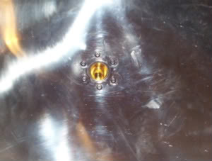
I placed the elbow and a flange nut in a citric acid bath overnight, to ensure it was clean. I applied some JB Weld to the thread of the elbow and then attached the flange nut facing upwards, smoothing any JB Weld that was squeezed from the joint and allowed it to dry overnight. The flange nut is going to be attached from underneath the tun using 6 x M3 x 12mm button head bolts, nuts and spring washers, JB Weld will be used to form the seal being applied to the mating surfaces of the flange nut, tun, and elbow/flange nut combo, as in the mock up. I drilled 6 x 3mm holes in the flange nut.
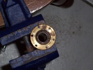
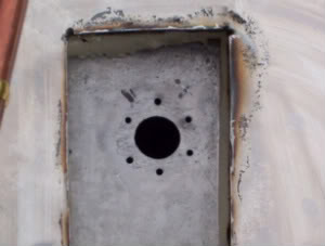
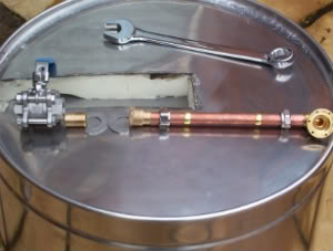
I masked the area immediately surrounding the previously drilled outlet hole in the inner skin of the tun, and secured the flange nut in position using a ½" nipple. I drilled through the holes in the flange nut, through the inner skin. These were the holes that I had all the trouble with. I removed burrs from the holes with my dremmel and keyed the mating surface with the dremmel also. I was now in a position to fit the tap and outlet assembly (see above right picture for exploded assembly) for easy reference.
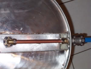
The washers have been cut down as the inner washer wouldn't fit neatly under the lip of the base of the thermo box and the outer washer went over the recess on the outside base of the thermo box. I applied plenty of PTFE tape to the nipple before screwing it into the ball valve. I pushed the ball valve nipple through the hole in the tun, and secured it with the coupler from the rear, using plenty of PTFE tape on the nipple before doing so. I then offered the outlet elbow to it's position on the inner skin. This gave me the length of 15mm copper pipe required to connect the outlet to the ball valve.
I cut the pipe to length and then re-offered it to the elbow/valve combo to ensure that it all lined up. I treated the mating area of the elbow, the 6 bolts, nuts and washers to a citric acid bath and dry to get rid of any grease on their surfaces and also cleaned the mating surface of the thermo box with acid also. I liberally applied JB Weld to the elbows flange nut, and aligned it with the holes in the inner skin of the thermo box. I applied a small amount of JB to the button head of the bolt and passed them through the inner skin, securing on the underside of the thermo box with the spring washer and nut. On passing the bolt through an amount of JB came through with the bolt and this was enough to seal the bolt/nut/washer combo on tightening. It was then a case of tightening the compression fittings.
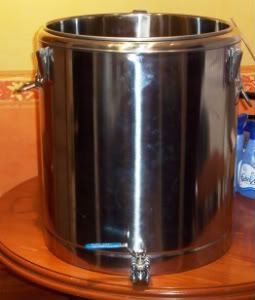
I placed the thermo box upside down and put a tea light candle inside it to speed up the drying process, leaving the valve open to allow hot gases to escape. It was tested for water tightness the following morning, and there were no leaks. I filled the void around the drain assembly with expanding foam, and used a small piece of stainless sheet to seal the area, so as to minimise heat loss.
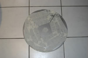
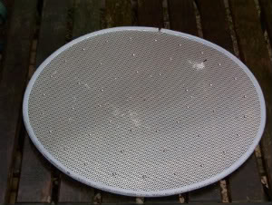
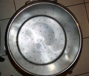
I also bought a made to measure false bottom for the tun, which was supplied by John at the Hop & Grape. It was cut at 443mm, which I measured as the mash tuns interior circumference. I double checked the circumference by making a 'mock up' of the false bottom out of cardboard to make sure the measurement was correct before ordering. It has standard 3/8th beer line around the outer edge to take up any anomalies in the tuns circular shape, and it fits perfectly. It was supplied with no legs or handle as requested. I mapped out the leg positions using masking tape and then drilled 3mm holes in those positions. I used M3 x 6mm button head bolts as legs, secured with M3 spring washers and nuts.
NOTE: At the time of making this item JB Weld was, and still is, my option for use as a sealant. It is classed as inert once cured, but has not been tested as food safe. The reason for me using it is that I wanted the smallest rigid seal I could get with minimal surface area exposed to the process. I could have used food grade silicone sealant, but in my experience I have yet to use a mould PROOF silicone sealant, so as the brewery is always wet, silicone sealant was/is not an option. Whilst plastic and rubber washers are available, I view their potential leaching properties in just the same light as JB Weld.
It's a personal choice as to what to use, I chose JB Weld.
Thanks to Vossy for this article
Copyright Information: This site designed by Jim Dunleavy